| # | nasa_id | caption | verdict | seed | title | orig_description | license | center | date_created | image_width | image_height | image_url | image_bytes |
|---|
1
|
0100057
|
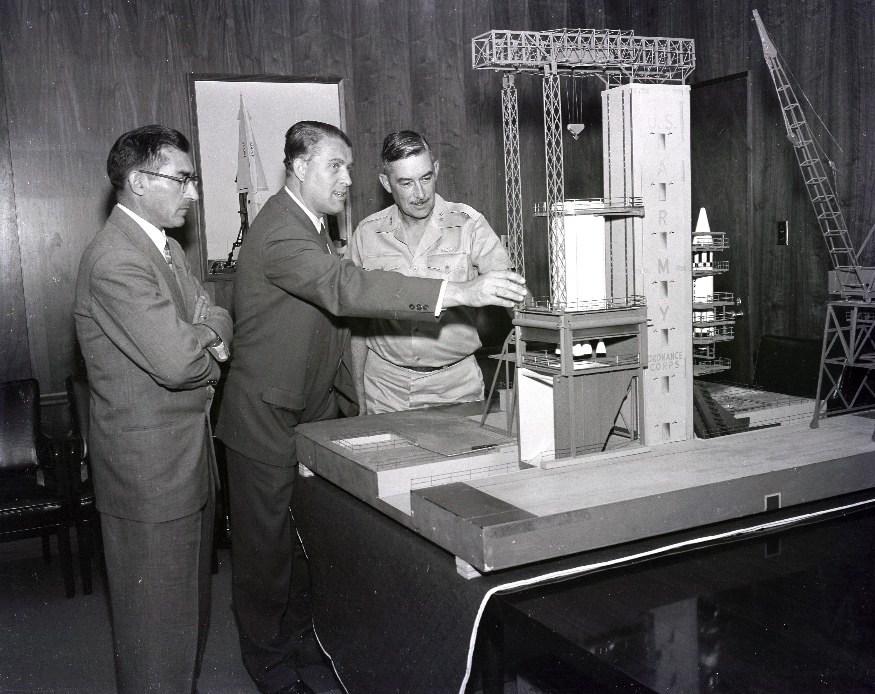
Three men stand around a large architectural model of a rocket launch facility, examining the structure. The central figure, wearing a dark suit, points toward a white cylindrical tower labeled "U.S. AIR FORCE ORDNANCE CORPS" in vertical lettering. A lattice-work gantry crane structure sits atop the tower, with a smaller model rocket visible on a service platform to the right. The man on the left, wearing glasses and a suit, observes with his arms crossed, while the man on the right, dressed in a light-colored military uniform, looks on. The model rests on a dark table, and a framed photograph of a rocket stands against the wood-paneled wall in the background.
|
DROP
|
(From left to right) Karl L. Heimburg, Director of the Test Laboratory; Dr. Wernher von Braun, Director of the Development Operation Division; and Major General John B. Medaris with the model of S-1B Test Stand. Gen. Medaris was a Commander of the Army Ballistic Missile Agency (ABMA) in Redstone Arsenal, Alabama, during 1955 to 1958.
|
Origin of Marshall Space Flight Center (MSFC)
|
(From left to right) Karl L. Heimburg, Director of the Test Laboratory; Dr. Wernher von Braun, Director of the Development Operation Division; and Major General John B. Medaris with the model of S-1B Test Stand. Gen. Medaris was a Commander of the Army Ballistic Missile Agency (ABMA) in Redstone Arsenal, Alabama, during 1955 to 1958.
|
PD
|
MSFC
|
1958-01-01T00:00:00Z
|
|
|
https://images-assets.nasa.gov/image/0100057/0100057~orig.jpg
|
|
2
|
GRC-1958-C-47803
|
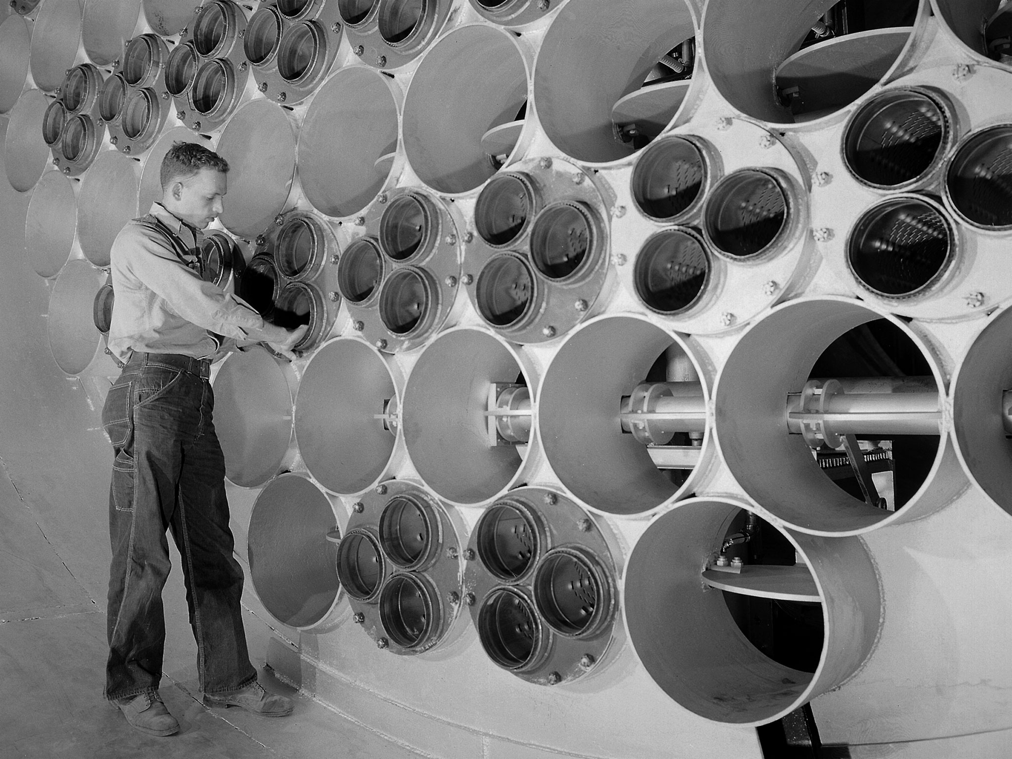
A technician in jeans and a light shirt stands before the massive, bolted metal structure of the 10- by 10-Foot Supersonic Wind Tunnel at the NACA Lewis Flight Propulsion Laboratory. He reaches into a cluster of small, circular observation ports set into the wall of large cylindrical ducts. The facility, constructed under the Congressional Unitary Plan Act, was the largest of three NACA tunnels built to test jet engines up to five feet in diameter. The array of large tubes and instrument windows illustrates the immense scale required to generate supersonic airflow for propulsion research.
|
KEEP
|
The 10- by 10-Foot Supersonic Wind Tunnel at the NACA Lewis Flight Propulsion Laboratory was built under the Congressional Unitary Plan Act which coordinated wind tunnel construction at the NACA, Air Force, industry, and universities. The 10- by 10, which began operation in 1956, was the largest of the three NACA tunnels built under the act. Researchers could test engines up to five feet in diameter in the 10- by 10-foot test section. A 250,000-horsepower axial-flow compressor fan can generate airflows up to Mach 3.5 through the test section. The incoming air must be dehumidified and cooled so that the proper conditions are present for the test. A large air dryer with 1,890 tons of activated alumina soaks up 1.5 tons of water per minute from the airflow. A cooling apparatus equivalent to 250,000 household air conditioners is used to cool the air. The air heater is located just upstream from the test section. Natural gas is combusted in the tunnel to increase the air temperature. The system could only be employed when the tunnel was run in its closed-circuit propulsion mode.
|
Preheater in the 10-by 10-Foot Supersonic Wind Tunnel
|
The 10- by 10-Foot Supersonic Wind Tunnel at the NACA Lewis Flight Propulsion Laboratory was built under the Congressional Unitary Plan Act which coordinated wind tunnel construction at the NACA, Air Force, industry, and universities. The 10- by 10, which began operation in 1956, was the largest of the three NACA tunnels built under the act. Researchers could test engines up to five feet in diameter in the 10- by 10-foot test section. A 250,000-horsepower axial-flow compressor fan can generate airflows up to Mach 3.5 through the test section. The incoming air must be dehumidified and cooled so that the proper conditions are present for the test. A large air dryer with 1,890 tons of activated alumina soaks up 1.5 tons of water per minute from the airflow. A cooling apparatus equivalent to 250,000 household air conditioners is used to cool the air. The air heater is located just upstream from the test section. Natural gas is combusted in the tunnel to increase the air temperature. The system could only be employed when the tunnel was run in its closed-circuit propulsion mode.
|
PD
|
GRC
|
1958-04-23T00:00:00Z
|
|
|
https://images-assets.nasa.gov/image/GRC-1958-C-47803/GRC-1958-C-47803~orig.jpg
|
|
3
|
GRC-1958-C-49377
|
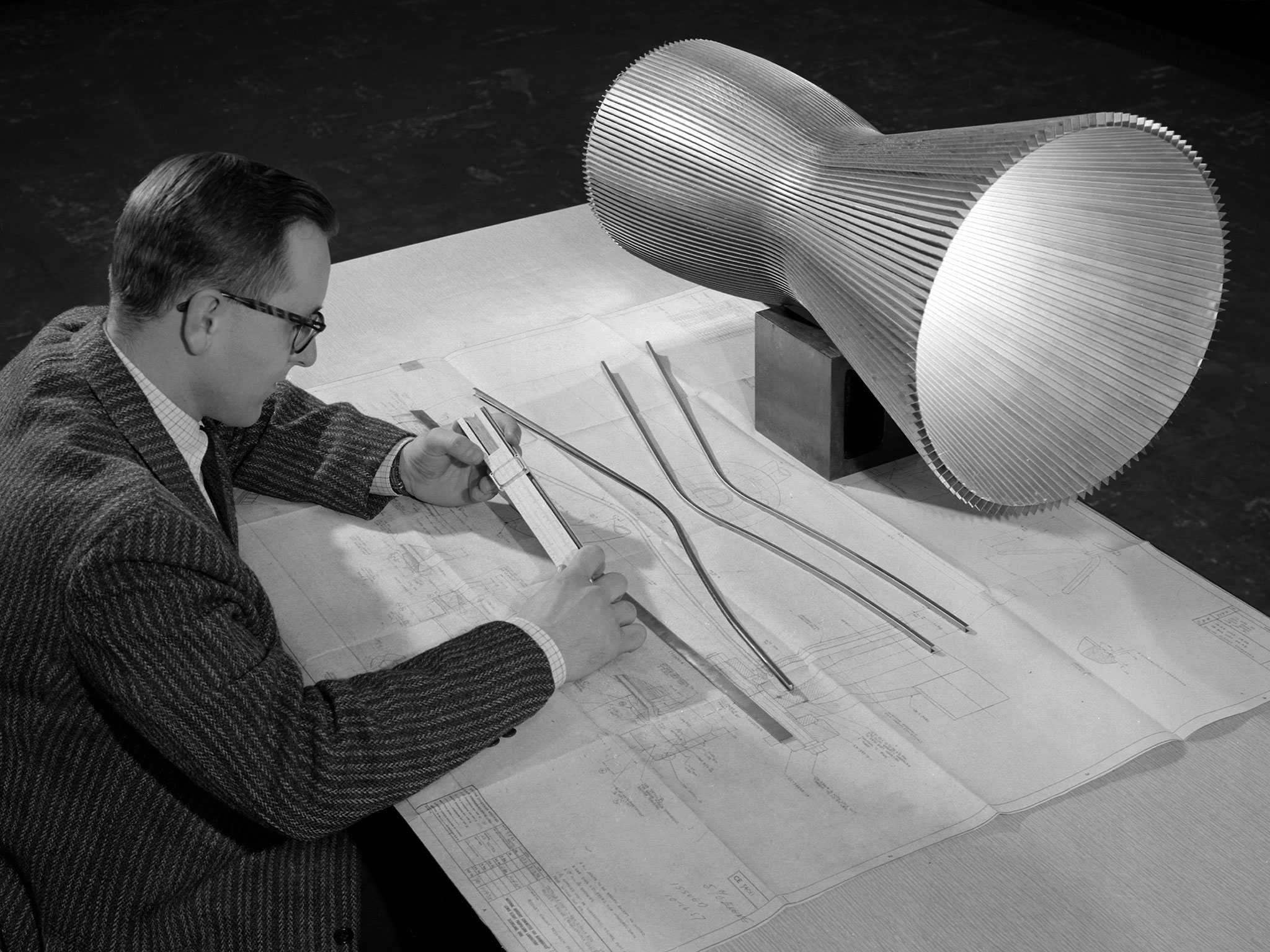
A man in a tweed jacket and glasses sits at a table covered in technical drawings, examining a small component while a large, ribbed metal nozzle model stands on a block nearby. Several long, curved metal tubes lie on the blueprints, representing the narrow channels used in regeneratively cooled rocket engines. In this design, cryogenic liquid hydrogen circulates through the tubes to cool the combustion chamber and nozzle before being ignited as propellant. The workspace features designs for a 20,000-pound thrust liquid-hydrogen engine, the Pratt and Whitney RL-10, developed at NASA Lewis Research Center. This technology was essential for the Centaur upper stage rocket and contributed to the development of the Saturn V upper stages.
|
KEEP
|
An engineer at the National Aeronautics and Space Administration (NASA) Lewis Research Center examines a drawing showing the assembly and details of a 20,000-pound thrust regeneratively cooled rocket engine. The engine was being designed for testing in Lewis’ new Rocket Engine Test Facility, which began operating in the fall of 1957. The facility was the largest high-energy test facility in the country that was capable of handling liquid hydrogen and other liquid chemical fuels. The facility’s use of subscale engines up to 20,000 pounds of thrust permitted a cost-effective method of testing engines under various conditions. The Rocket Engine Test Facility was critical to the development of the technology that led to the use of hydrogen as a rocket fuel and the development of lightweight, regeneratively-cooled, hydrogen-fueled rocket engines. Regeneratively-cooled engines use the cryogenic liquid hydrogen as both the propellant and the coolant to prevent the engine from burning up. The fuel was fed through rows of narrow tubes that surrounded the combustion chamber and nozzle before being ignited inside the combustion chamber. The tubes are visible in the liner sitting on the desk. At the time, Pratt and Whitney was designing a 20,000-pound thrust liquid-hydrogen rocket engine, the RL-10. Two RL-10s would be used to power the Centaur second-stage rocket in the 1960s. The successful development of the Centaur rocket and the upper stages of the Saturn V were largely credited to the work carried out Lewis.
|
NASA Engineer Examines the Design of a Regeneratively-Cooled Rocket Engine
|
An engineer at the National Aeronautics and Space Administration (NASA) Lewis Research Center examines a drawing showing the assembly and details of a 20,000-pound thrust regeneratively cooled rocket engine. The engine was being designed for testing in Lewis’ new Rocket Engine Test Facility, which began operating in the fall of 1957. The facility was the largest high-energy test facility in the country that was capable of handling liquid hydrogen and other liquid chemical fuels. The facility’s use of subscale engines up to 20,000 pounds of thrust permitted a cost-effective method of testing engines under various conditions. The Rocket Engine Test Facility was critical to the development of the technology that led to the use of hydrogen as a rocket fuel and the development of lightweight, regeneratively-cooled, hydrogen-fueled rocket engines. Regeneratively-cooled engines use the cryogenic liquid hydrogen as both the propellant and the coolant to prevent the engine from burning up. The fuel was fed through rows of narrow tubes that surrounded the combustion chamber and nozzle before being ignited inside the combustion chamber. The tubes are visible in the liner sitting on the desk. At the time, Pratt and Whitney was designing a 20,000-pound thrust liquid-hydrogen rocket engine, the RL-10. Two RL-10s would be used to power the Centaur second-stage rocket in the 1960s. The successful development of the Centaur rocket and the upper stages of the Saturn V were largely credited to the work carried out Lewis.
|
PD
|
GRC
|
1958-12-23T00:00:00Z
|
|
|
https://images-assets.nasa.gov/image/GRC-1958-C-49377/GRC-1958-C-49377~orig.jpg
|
|
4
|
9248170
|
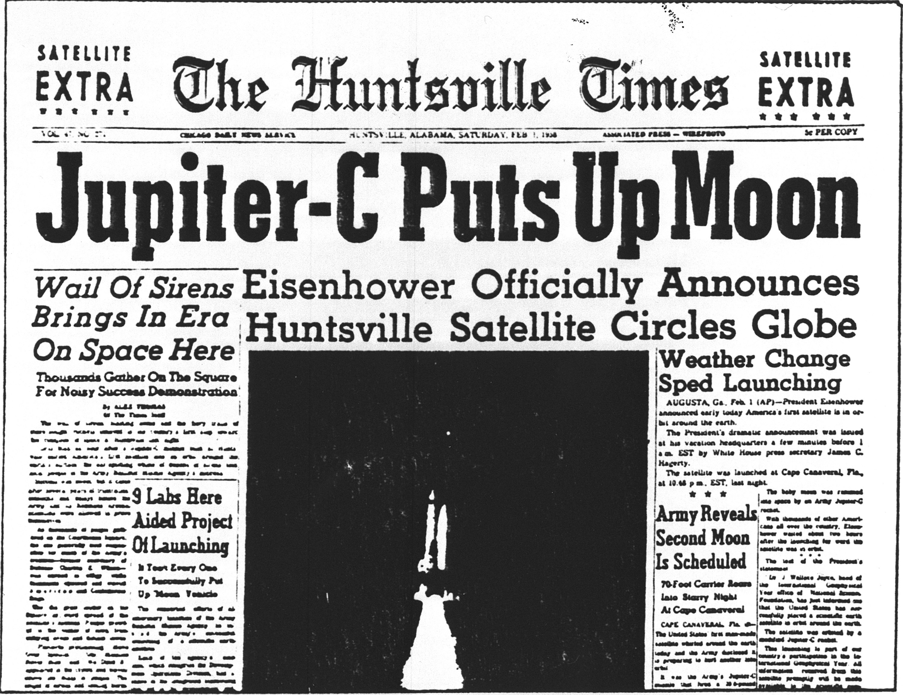
The front page of The Huntsville Times features the bold headline "Jupiter-C Puts Up Moon" above a central photograph of a rocket launching vertically against a dark background. The masthead identifies the publication as a "Satellite Extra" edition, with smaller headlines announcing that Eisenhower officially announced the Huntsville satellite circles the globe and that the Army revealed a second moon is scheduled. A column of text on the right details the weather change that sped the launching, while the left column reports on the wail of sirens and the gathering of thousands for the demonstration. The central image shows the white rocket ascending with a plume of exhaust at its base, flanked by two vertical structures on the launch pad.
|
DROP
|
In January 1958, a modified Redstone rocket lifted the first American satellite into orbit just 3 months after the the von Braun team received the go-ahead. This modified Redstone rocket was known as a Jupiter-C. Its satellite payload was called Explorer I.
|
Early Rockets
|
In January 1958, a modified Redstone rocket lifted the first American satellite into orbit just 3 months after the the von Braun team received the go-ahead. This modified Redstone rocket was known as a Jupiter-C. Its satellite payload was called Explorer I.
|
PD
|
MSFC
|
1958-01-01T00:00:00Z
|
|
|
https://images-assets.nasa.gov/image/9248170/9248170~orig.jpg
|
|
5
|
LRC-1958-B701_P-01966
|
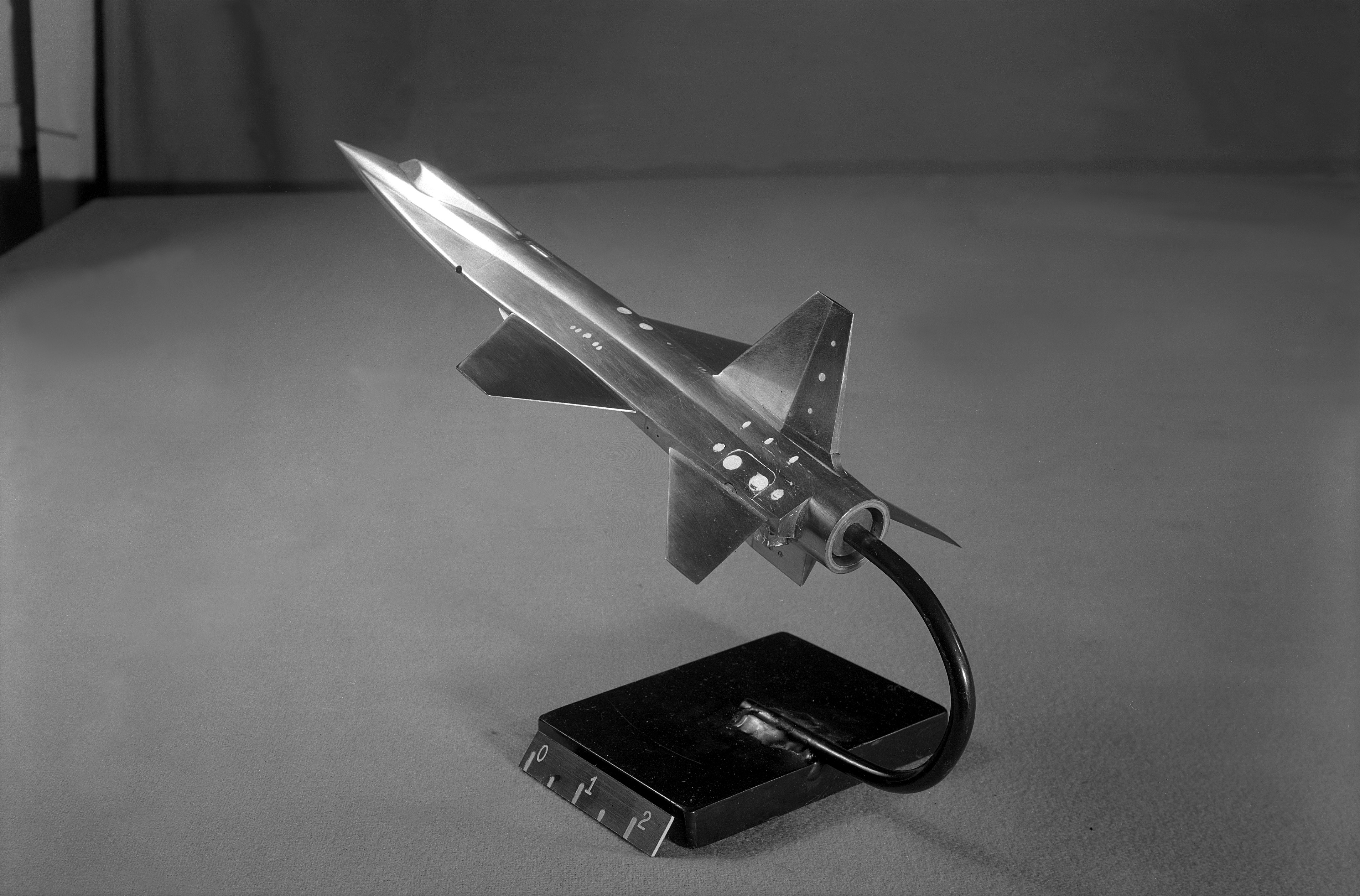
A metallic scale model of the initial X-15 design rests on a black display stand, mounted by a curved rod attached to the rear engine nozzle. The aircraft features a sharp, pointed nose, swept wings, and a vertical stabilizer, with distinctive side-tunnels running along the fuselage and extending far forward toward the nose. A small ruler attached to the front of the base displays markings for 0, 1, and 2. This model represents North American's early configuration, which underwent testing in North American and NACA wind tunnels. Aeronautical testing by Langley engineers confirmed that the side-tunnels made the design less stable, while North American engineers determined the variable wedge-angle stabilizer created a weight issue.
|
KEEP
|
This scale-model of North American's initial X-15 design was tested in North American and NACA wind tunnels note the conventional tail and fuselage side-tunnels that extend far toward the aircraft nose. North American engineers would determine that the variable wedge-angle stabilizer created a weight issue, and aeronautical testing by Langley engineers confirmed that the side-tunnels made the design less stable.
|
X-15 Configurations
|
This scale-model of North American's initial X-15 design was tested in North American and NACA wind tunnels note the conventional tail and fuselage side-tunnels that extend far toward the aircraft nose. North American engineers would determine that the variable wedge-angle stabilizer created a weight issue, and aeronautical testing by Langley engineers confirmed that the side-tunnels made the design less stable.
|
PD
|
LRC
|
1958-05-06T00:00:00Z
|
3818
|
2516
|
https://images-assets.nasa.gov/image/LRC-1958-B701_P-01966/LRC-1958-B701_P-01966~orig.tif
|
|
6
|
0100075
|
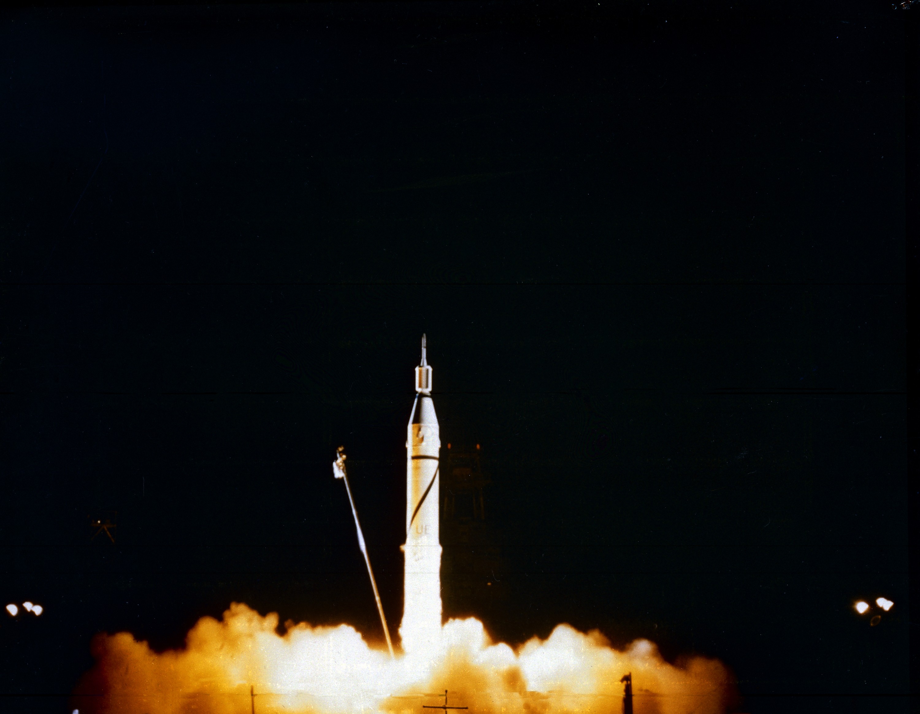
A white rocket stands vertically against a dark night sky, its engines firing to produce a massive, glowing cloud of orange and yellow exhaust at the base. A slender, angled service arm extends from the left side toward the rocket's midsection. The vehicle features a pointed nose cone and a cylindrical body with visible panel lines and markings. Distant lights are visible on the horizon to the left and right, illuminating the edges of the launch site.
|
DROP
|
Launch of Jupiter-C/Explorer 1 at Cape Canaveral, Florida on January 31, 1958. After the Russian Sputnik 1 was launched in October 1957, the launching of an American satellite assumed much greater importance. After the Vanguard rocket exploded on the pad in December 1957, the ability to orbit a satellite became a matter of national prestige. On January 31, 1958, slightly more than four weeks after the launch of Sputnik.The ABMA (Army Ballistic Missile Agency) in Redstone Arsenal, Huntsville, Alabama, in cooperation with the Jet Propulsion Laboratory, launched a Jupiter from Cape Canaveral, Florida. The rocket consisted of a modified version of the Redstone rocket's first stage and two upper stages of clustered Baby Sergeant rockets developed by the Jet Propulsion Laboratory and later designated as Juno boosters for space launches
|
Early Rockets
|
Launch of Jupiter-C/Explorer 1 at Cape Canaveral, Florida on January 31, 1958. After the Russian Sputnik 1 was launched in October 1957, the launching of an American satellite assumed much greater importance. After the Vanguard rocket exploded on the pad in December 1957, the ability to orbit a satellite became a matter of national prestige. On January 31, 1958, slightly more than four weeks after the launch of Sputnik.The ABMA (Army Ballistic Missile Agency) in Redstone Arsenal, Huntsville, Alabama, in cooperation with the Jet Propulsion Laboratory, launched a Jupiter from Cape Canaveral, Florida. The rocket consisted of a modified version of the Redstone rocket's first stage and two upper stages of clustered Baby Sergeant rockets developed by the Jet Propulsion Laboratory and later designated as Juno boosters for space launches
|
PD
|
MSFC
|
1958-01-31T00:00:00Z
|
|
|
https://images-assets.nasa.gov/image/0100075/0100075~orig.jpg
|
|
7
|
6414024
|
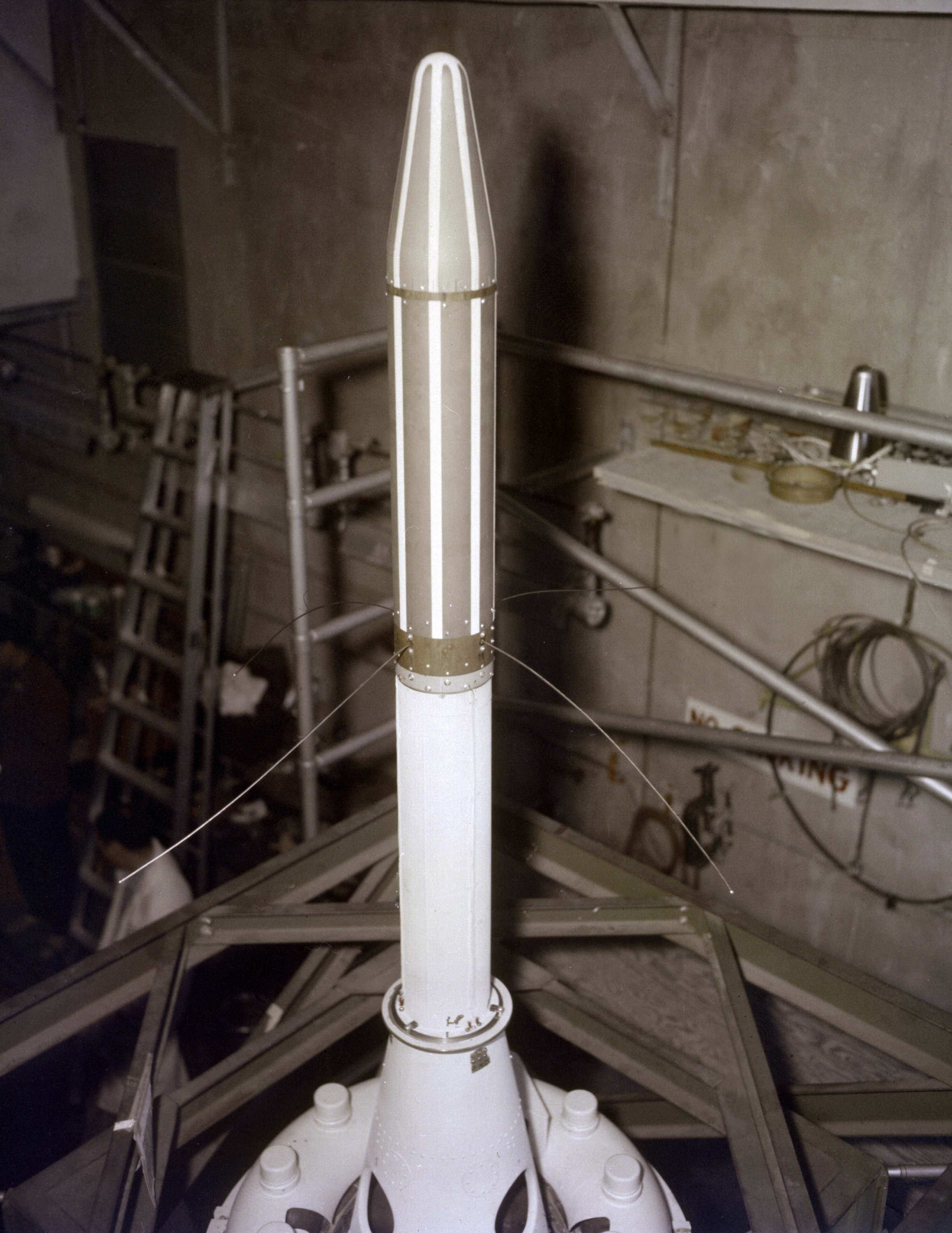
The Explorer 1 satellite stands vertically, its slender white body topped by a pointed aerodynamic nose cone. Below the nose cone, a section features vertical ribs, while thin wire antennas extend outward from the midsection. The base of the satellite rests on a wider support structure with four small white knobs visible around the perimeter. The satellite is positioned within an industrial facility, surrounded by metal scaffolding, ladders, and concrete walls. As the first United States Earth-orbiting satellite, it is shown here during installation onto its Jupiter-C launch vehicle.
|
KEEP
|
Explorer 1 satellite. This photo was taken during the installation of Explorer-1, the first United States' Earth-orbiting satellite, to its launch vehicle, Jupiter-C, in January 1958
|
Early Rockets
|
Explorer 1 satellite. This photo was taken during the installation of Explorer-1, the first United States' Earth-orbiting satellite, to its launch vehicle, Jupiter-C, in January 1958
|
PD
|
MSFC
|
1958-01-01T00:00:00Z
|
|
|
https://images-assets.nasa.gov/image/6414024/6414024~orig.jpg
|
|
8
|
E-3361
|
A pilot in a pressure suit and helmet stands beside the nose of a sleek, white experimental aircraft, pointing toward the fuselage markings. The aircraft features a pointed nose cone, a bubble canopy, and a tricycle landing gear configuration. Large black lettering on the side reads "X-1E" and "LITTLE JOE," while a graphic to the left displays the text "OTHER RESCUE SIDE" within a double-headed arrow. The pilot wears a full-body suit with an oxygen hose and heavy boots, standing on a paved tarmac under bright sunlight.
|
DROP
|
Joe Walker in a pressure suit beside the X-1E at the NASA High-Speed Flight Station, Edwards,California. The dice and "Little Joe" are prominently displayed under the cockpit area. (Little Joe is a dice players slang term for two deuces.) Walker is shown in the photo wearing an early Air Force partial pressure suit. This protected the pilot if cockpit pressure was lost above 50,000 feet. Similar suits were used in such aircraft as B-47s, B-52s, F-104s, U-2s, and the X-2 and D-558-II research aircraft. Five years later, Walker reached 354,200 feet in the X-15. Similar artwork - reading "Little Joe the II" - was applied for the record flight. These cases are two of the few times that research aircraft carried such nose art.
|
Joe Walker in pressure suit with X-1E
|
Joe Walker in a pressure suit beside the X-1E at the NASA High-Speed Flight Station, Edwards,California. The dice and "Little Joe" are prominently displayed under the cockpit area. (Little Joe is a dice players slang term for two deuces.) Walker is shown in the photo wearing an early Air Force partial pressure suit. This protected the pilot if cockpit pressure was lost above 50,000 feet. Similar suits were used in such aircraft as B-47s, B-52s, F-104s, U-2s, and the X-2 and D-558-II research aircraft. Five years later, Walker reached 354,200 feet in the X-15. Similar artwork - reading "Little Joe the II" - was applied for the record flight. These cases are two of the few times that research aircraft carried such nose art.
|
PD
|
AFRC
|
1958-01-27T00:00:00Z
|
3000
|
2733
|
https://images-assets.nasa.gov/image/E-3361/E-3361~orig.jpg
|

|
9
|
LRC-1958-B701_P_F001-02984
|
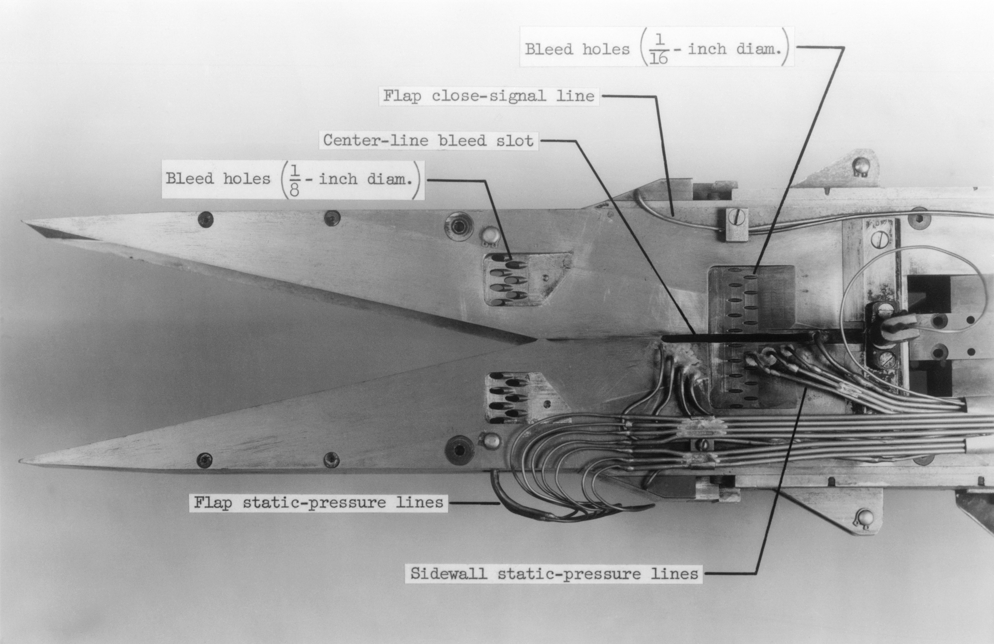
A cutaway view of an aircraft wing section reveals the internal structure and instrumentation used for aerodynamic testing. The metallic wing features a sharp leading edge and a trailing edge equipped with flaps. Numerous labels identify specific components, including "Bleed holes (1/8 - inch diam.)" and "Bleed holes (1/16 - inch diam.)" located near the leading edge. A "Center-line bleed slot" runs along the wing's midsection, while a "Flap close-signal line" is positioned near the trailing edge. Bundles of tubing labeled "Flap static-pressure lines" and "Sidewall static-pressure lines" connect to the internal mechanisms, routing data from the wing's surface to the instrumentation.
|
DROP
|
Mach number 6.9 Inlet. These negatives in jackets also: L-1958-2984.1 Figure 3b cone in NASA document L-1643 L-1958-2980.1 Figures 3a in document L-1643 declassified from Confidential
|
Mach number 6.9 Inlet
|
Mach number 6.9 Inlet. These negatives in jackets also: L-1958-2984.1 Figure 3b cone in NASA document L-1643 L-1958-2980.1 Figures 3a in document L-1643 declassified from Confidential
|
PD
|
LRC
|
1958-07-08T00:00:00Z
|
4000
|
2594
|
https://images-assets.nasa.gov/image/LRC-1958-B701_P_F001-02984/LRC-1958-B701_P_F001-02984~orig.tif
|
|
10
|
LRC-1958-B701_P-01150
|
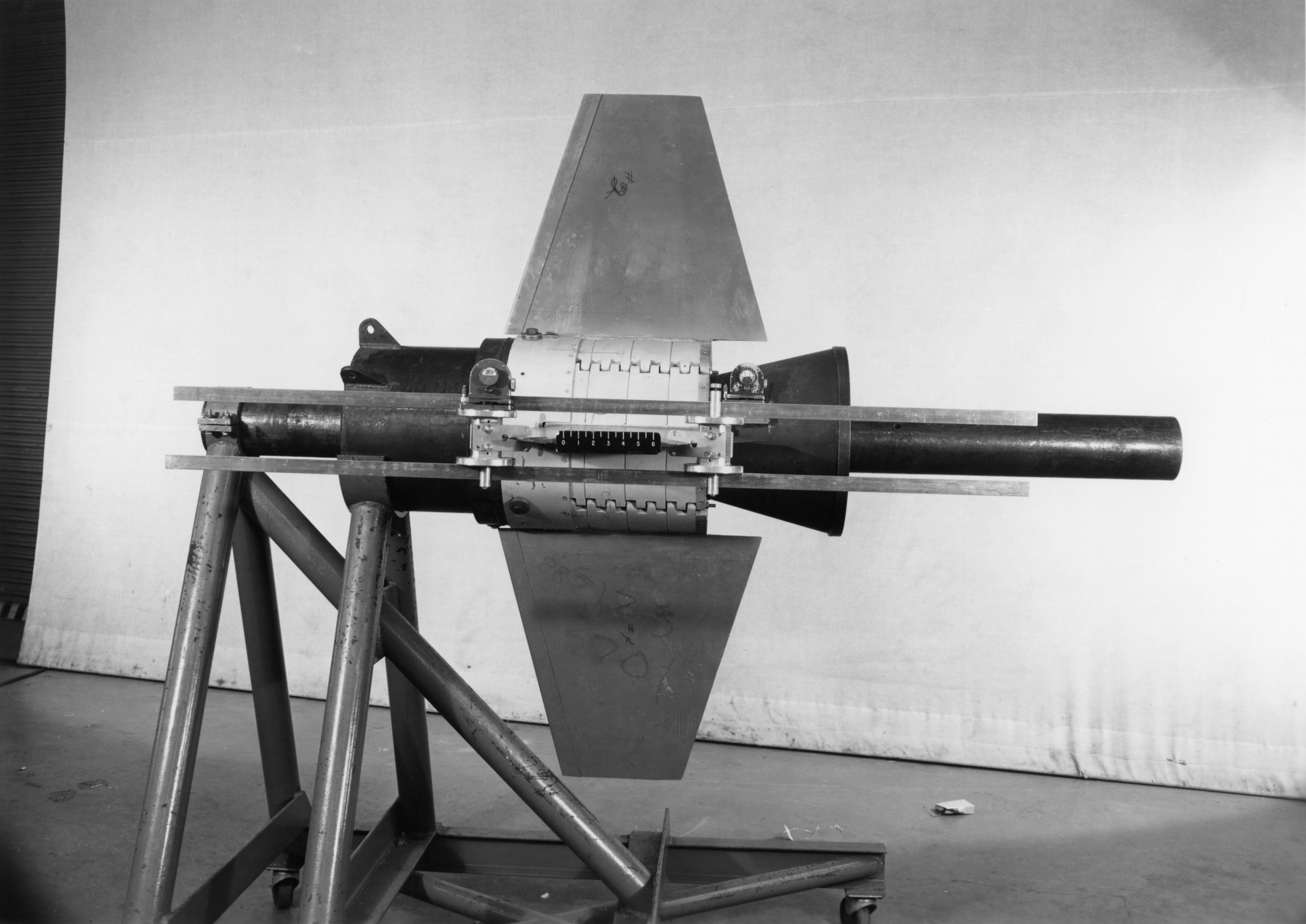
A rocket engine test article sits mounted on a heavy steel truss stand against a plain white wall. The central cylindrical body features a segmented metallic band with a serrated or corrugated texture, flanked by dark, smooth sections. Two large, trapezoidal fins extend vertically from the midsection, one pointing upward and the other downward. A long, dark cylindrical nozzle protrudes to the right, while a shorter section extends to the left. Two thin metal bars run horizontally across the assembly, passing in front of the nozzle and behind the central body. Faint handwritten markings are visible on the surface of the lower fin.
|
DROP
|
Photographed on: 12 09 58. -- Mercury capsule details, capsule in cargo bay of C-130 airplane prior to drop test, equipment in C130 for doing drop test.
|
C-130 drop tests capsule #1
|
Photographed on: 12 09 58. -- Mercury capsule details, capsule in cargo bay of C-130 airplane prior to drop test, equipment in C130 for doing drop test.
|
PD
|
LRC
|
1958-12-09T00:00:00Z
|
5497
|
3890
|
https://images-assets.nasa.gov/image/LRC-1958-B701_P-01150/LRC-1958-B701_P-01150~orig.tif
|
|